
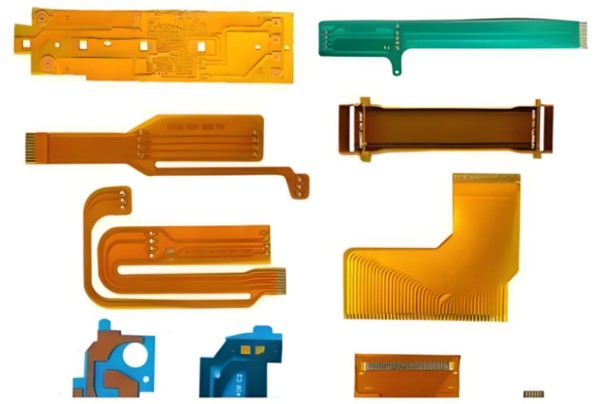
FPC (Flexible Printed Circuit) refers to a flexible printed circuit board. It is manufactured by forming conductive circuit patterns on a bendable substrate surface through photoimaging pattern transfer and etching processes. For double-sided and multi-layer boards, electrical connections between surface and inner layers are achieved via plated through holes. The circuit patterns are protected and insulated by a surface coating of PI material. FPCs offer a highly flexible, bendable, thin, lightweight, and space-saving electronic interconnection solution. With the trend toward miniaturization, slimness, and portability in electronics, FPCs are increasingly widely used in electronic devices.
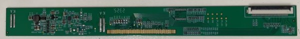
TCON is primarily the timing controller for TFT displays. Circuits related to TCON can also be designed on FPCs, which typically enables higher production yields and lower costs. TCON boards may alternatively use polyimide materials or FR4 (fiberglass epoxy), but these compromise flexibility and thinness while increasing relative costs.
Defining Custom Design Requirements
Custom FPC design must begin with clarifying practical application needs:
The FPC’s dimensions and structure must match the customer’s end-product design. Via placement should be optimized to ensure connection reliability and ease of assembly. Material choice critically impacts FPC performance and lifespan. Common materials include:
- Polyester film (PET)
- Polyimide (PI)
- Polyvinyl chloride (PVC)
Example: PI offers excellent insulation, high-temperature resistance, and flex endurance, making it ideal for FPCs. Materials should be selected based on application-specific tradeoffs.
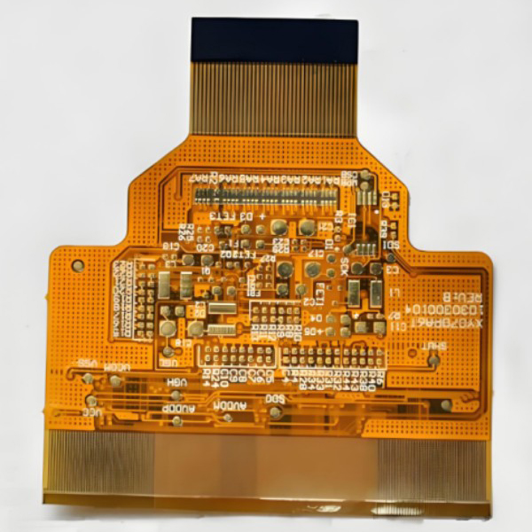
Design must account for operating environment, temperature, load current, voltage, etc., to ensure electrical functionality. Critical considerations include: Minimizing conductor length to reduce signal delay and power loss. Avoiding conductor crossover/overlap to minimize electromagnetic interference (EMI) and crosstalk.
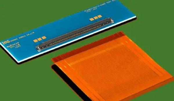
FPC and Connector Design
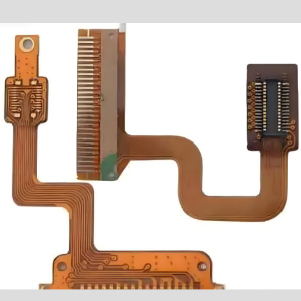
FPC connectors specialize in interfacing FPC with PCBs. They offer multiple contact options: pins, sockets, card-edge contacts, solder tabs, and single/dual-row housing designs. Some variants support hybrid connections for FFCs and round wires. Available pitches include 0.3mm, 0.5mm, 1.00mm, 1.25mm, and 2.54mm. The most common pitches are 0.500mm, 1.00mm, and 1.25mm.
FPC EMC Design
To mitigate electromagnetic interference (EMC):
- Apply shielding films to the FPC surface.
-Integrate dedicated anti-interference circuits for TCON-functional FPCs.
Conclusion.
FPC design requires holistic consideration of: Design requirements, Material selection, Circuit layout, Simulation, Routing and interconnects, Optimization and verification. A systematic design process with meticulous attention to detail ensures FPCs deliver robust performance, longevity, and application suitability.


